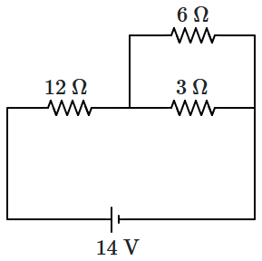
In the circuit shown in the figure below, the current supplied by the battery is:

1. \(2~\text A\)
2. \(1~\text A\)
3. \(0.5~\text A\)
4. \(0.4~\text A\)
A cell having an emf \(\varepsilon\) and internal resistance \(r\) is connected across a variable external resistance \(R\). As the resistance \(R\) is increased, the plot of potential difference \(V\) across \(R\) is given by:
| 1. |  |
2. |  |
| 3. |  |
4. |  |
A potentiometer is an accurate and versatile device to make electrical measurements of E.M.F. because the method involves:
| 1. | the potential gradients. |
| 2. | a condition of no current flow through the galvanometer. |
| 3. | a condition of cells, galvanometer, and resistances. |
| 4. | the cells. |
The metre bridge shown is in a balanced position with \(\frac{P}{Q} = \frac{l_1}{l_2}\). If we now interchange the position of the galvanometer and the cell, will the bridge work? If yes, what will be the balanced condition?
| 1. | Yes, \(\frac{P}{Q}=\frac{l_1-l_2}{l_1+l_2}\) | 2. | No, no null point |
| 3. | Yes, \(\frac{P}{Q}= \frac{l_2}{l_1}\) | 4. | Yes, \(\frac{P}{Q}= \frac{l_1}{l_2}\) |
| 1. | \(4v\) | 2. | \(8v\) |
| 3. | \(v\) | 4. | \(2v\) |
| 1. | \((10\pm4.2)~\Omega \) | 2. | \((10\pm0.3)~\Omega \) |
| 3. | \((10\pm0.1)~\Omega \) | 4. | \((10\pm0.8)~\Omega \) |
| 1. | \(2:9\) | 2. | \(1:2\) |
| 3. | \(2:3\) | 4. | \(1:1\) |
Power consumed in the given circuit is \(P_1.\) On interchanging the position of \(3~\Omega\) and \(12~\Omega\) resistances, the new power consumption is \(P_2.\) The ratio of \(\dfrac{P_2}{P_1}\) is:

| 1. | \(2\) | 2. | \(\dfrac 12\) |
| 3. | \(\dfrac 35\) | 4. | \(\dfrac 25\) |
The total current supplied to the circuit by the battery is:

1. \(1~\text{A}\)
2. \(2~\text{A}\)
3. \(4~\text{A}\)
4. \(6~\text{A}\)
| 1. | \(1000\) | 2. | \(10\) |
| 3. | \(100\) | 4. | \(1\) |


